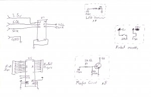
 There are several elements to the pinball circuit. First, it should be noted that this circuit doesn’t bother with lights. All it’s concerned with are the main assemblies, and their controls.
So, on the top left side of the figure is the logic level converter. It’s not really an IC, just a small board with SMT parts (somewhat like a Basic Stamp) that I got from AdaFruit. Basically, you give it a common ground, and two different VDD voltages, and it can convert logic in both directions. I’m using it to convert from the Raspberry Pi’s 3.3VDC to the MCP23017’s 5VDC which is also the level used on all the switch circuitry in the whole machine.
On the Bottom Left is the MCP23017, which has 2 GPIO ports of 8bits each. Port B I am using for reading the switches, and Port A I am using to drive the MOSFET array.
On the Bottom Right is an example of one instance of the MOSFET circuit that creates the whole array. When 5v is applied to the input, it allows the HV from the solenoid to flow to ground. The resistors are in there for voltage padding, and to drain the slight capacitance of the MOSFET.
On the top right is an example of the LEDs that I plan to hook into the output in order to indicate the status of the output registers. Perhaps useful in debugging. It’s also cool. 😀
On the middle right is a simple diagram of what most pinball assemblies look like. A simple switch pulls the output high. It is interesting to note that general pinball practice has the solenoids connected to the voltage all the time, but not until they are connected to ground do they fire.
So, if you happen to understand any of that, you are officially a geek! 😀
Be sure to check back soon, and if you are interested in the project, don’t forget to follow me on Twitter @marktbaldridge